|
______________________________________ DEFINITIONS ______________________________________ AXES OF MOVEMENT An aeroplane in flight moves around 3 axes; Longitudinal Axis---Rolling Plane, Ailerons. Vertical Axis---------Yawing Plane, Rudder. Horizontal Axis------Pitching Plane, Elevator. ______________________________________ CENTRE OF GRAVITYThe common point of balance for the three planes of movement. The three axes of movement pass through this point. There are four primary forces that act on an aeroplane in flight; (i) LIFT A force generated by the passage of air over an aerofoil. This force acts on the aerofoil at 90 degrees to the relative airflow. (ii) WEIGHT Mass = 1 G., weight = mass x acceleration. (iii) THRUST The propelling force of the aeroplane which acts forward along the thrust axis. (iv) DRAG Resistance generated by motion between an object and the airflow - a force which acts rearward, aligned with the relative airflow. When an aeroplane is in level flight at a constant airspeed, the opposing primary forces are in balance; Lift = Weight Thrust = Drag. RELATIVE AIRFLOWThe airflow past an aeroplane in flight is aligned with the flight path. This alignment is not necessarily the alignment of the aeroplane - (due to inertia). AEROFOIL This term is used to describe the curved cross sectional design of an aeroplane wing. Normally, the cross sectional shape of an aeroplane wing is asymmetric, with the upper surface being convex and the lower surface flat. A propeller blade is an example of an aerofoil. CHORD LINE The chord line passes through an aerofoil from the leading edge to the trailing edge (a line that joins the two ends of an arc) and is the reference line for the lateral plane form (mainplane, tailplane etc.). ANGLE OF INCIDENCE This angle is measured between the longitudinal axis of the aeroplane and the mean chord line of the mainplane and likewise with the tailplane. The important consideration is the relationship between the angles of incidence of the mainplane and the tailplane. ANGLE OF ATTACK The angle formed between the mean chord line and the relative airflow. An increase in lift will result when the angle of attack is increased, with the increase occurring through the range from approximately -2 degrees to + 15 degrees (note minus 2). STALL If the angle of attack is increased beyond 16 degrees the smooth airflow over the upper cambered surface of the mainplane will begin to break away and become turbulent. This transition occurs abruptly once the angle of 16 degrees has been exceeded. At this point there is a sudden and dramatic loss of lift and a sudden and dramatic increase in drag - the mainplane is stalled. A conventional mainplane (excluding delta wing design) will stall at any subsonic speed if this critical angle of 16 degrees is exceeded. STALLING SPEED The speed at which the mainplane stalls. This value changes due to weight (mass x acceleration). SLIP, SKID These terms are used mainly in the context of describing flight path divergence resulting from out-of-balance forces during a turn. SIDESLIPThis term is used to describe the flight path which results from biased control inputs (a sideslip is used to precipitate an increase in the rate of descent without incurring an unwanted increase in airspeed). TRIM Out-of-balance forces frequently result from variations in load placement, power application, flap setting and airspeed, etc. There is, subsequently, a need to provide a facility to offset the flight control pressures that would otherwise have to be maintained by the pilot. The normal procedure is to employ adjustable trim tabs in the control surfaces, and/or adjustable spring tension bias in the control linkages. There are three primary flight control systems that may incorporate this facility (elevator, rudder, ailerons). RATE OF TURN This term refers to the amount of turn measured against time. A standard 'rate one turn' requires 2 minutes to complete a 360 degrees turn (3 degrees per sec.). Instrument approach, holding and landing procedures are normally formatted on the basis of 'rate one turns'. HEADING The heading of an aeroplane is expressed with reference to a magnetic compass in degrees, read clockwise from north (001-360). The reference for north can be either true or magnetic. TRACK The intended flight path is relation to the surface of the earth. TRACK MADE GOOD (TMG) The actual flight path in relation to the surface of the earth. In nil wind conditions, the TMG will be the same as the heading, but when subject to wind velocity, the TMG will diverge (except when encountering a direct head or tail wind). TRACK ERROR The angle measured between Track (track required) and TMG (track made good). DRIFT The angle measured between Heading and TMG. WIND VELOCITY This term implies two components - ie., wind speed and wind direction. AIRSPEED INDICATED AIRSPEED (IAS) is measured by a pressure (dynamic) sensing mechanism. A reading thus obtained will vary according to the speed through the air and on the divergence of air density values. To arrive at an accurate airspeed value, true airspeed (TAS) it is necessary to have a coefficient for air density. The adjustment can be calculated and applied to the indicated value, or more simply, the adjustment can be made direct to the airspeed indicator by rotating the calibrated face plate and aligning temperature and altitude references, and then reading the corrected TAS direct from the indicator. The difference between indicated airspeed and true airspeed becomes significant as altitude is gained, with TAS averaging an increase of about 1.7% of IAS per 1000 ft. above mean sea level. GROUND SPEED The speed of the aeroplane measured across the surface of the earth. In conditions of nil wind, ground speed will be the same as true airspeed. When subject to wind, the ground speed will vary with dependence on the incidence and speed of the wind. It is interesting to note that in conditions of wind, there is one headings that will result in the ground speed resolving to the same value as true airspeed. This situations occurs when the incidence of the wind is just behind an abeam position, (greater than 90 degrees measured between TMG and wind direction). This angle commences from very near an abeam line with low wind speed, and increases rearwards as the speed of the wind increases. RATE OF CLIMB The rate of climb refers to the gain in altitude achieved, measured against time. The normal expression is feet per minute. ANGLE OF CLIMB The angle of climb refers to the angle measured between the horizontal and the flight path. Wind velocity effects the angle of climb, but not the rate of climb. SPIN A spin is a condition of stalled flight and the aeroplane describes a vertical, spiral descent path. A spin is sometimes confused with a spiral dive because of similarities in nose attitude and flight path. However, there is one broad distinction between the two - 'airspeed'. During a spin, the airspeed remains stable at a very low value, (stalled) whereas in a spiral dive, the airspeed is usually very high - ("graveyard spiral"). SLIPSTREAM EFFECT The slipstream from a revolving propeller (single engine aeroplane) spirals rearwards, around the fuselage, striking the vertical fin and rudder on one side. This produces an unwanted turning effect known as 'Slipstream Effect' (sometimes confused with 'propeller torque'). This effect is experienced during the take-off roll and during certain aerobatic flight manoeuvres. The effect has greatest magnitude during the early stages of the take-off roll, where power application and propeller RPM are high and airspeed is low. Clockwise propeller rotation (as seen from the pilots seat) produces a yaw to the left. The effect is more pronounced in high powered aeroplanes. It is interesting to note that the 'Tempest' fighter of WW2 vintage, one of the most powerful fighter aeroplanes of WW2, required, during the early stages of the take-off roll, the application of differential brake in addition to full rudder deflection, - as well as delicate, metered throttle application in order to keep straight. PROPELLER TORQUE A force that opposes the rotation of the propeller (drag). In effect, a tendency for the aeroplane to rotate around the thrust line, in a direction opposite to the rotation of the propeller. Clockwise propeller rotation, (as seen from the pilots seat) produces a roll to the left. This force is significant only in respect of very high power engines during take-off and sometimes experienced during certain aerobatic manoeuvres where power application and propeller RPM are high and airspeed is low. GYROSCOPIC EFFECT The rotating mass of a crankshaft and propeller etc. generates gyroscopic stability in the plane of rotation and if an external force is applied to displace this state, then this external force is resisted, and the applied force is transferred 90º in the direction of rotation. The practical consideration can be best illustrated by referring to the yaw encountered when the nose of an aeroplane is abruptly raised during the final stage of the take-off run to facilitate a decisive and clean lift-off. When this occurs, it may be considered that the external force has been applied vertically from beneath. If the direction of rotation is clockwise, then the force will cause a yaw to the right. A further example can be seen in a situation where a tail wheel aeroplane has experienced the sudden application of full power for take-off, and almost immediately, the pilot abruptly lifts the tail. (With the application of full power and the use of large elevator deflection, sufficient force is generated to lift the tail, even though there is still very little forward speed.) The combination of low speed and high engine/propeller RPM provide the right circumstances, in this example, to generate a strong gyroscopic effect, and the aeroplane would experience a noticeable yaw. Counter measures are normally incorporated in the airframe design and rigging which partially offset the unwanted forces of slipstream effect, propeller torque and gyroscopic effect that are experienced during take-off. These offsets are somewhat compromised by the need to maintain aerodynamic balance in the cruising configuration, where most flight time is spent - for example; the fin could be offset, the thrust line could be offset and/or an outboard section of wing may be washed in to counteract the tendency to yaw or roll during take-off, but not at the expense of incurring out-of-balance forces in the cruising configuration. Many modern, multi engine aeroplanes employ counter rotating engines and propellers to alleviate the problems associated with slipstream effect, propeller torque and gyroscopic effect. INERTIA The property of inertia causes a body to remain in a state of rest or uniform motion until acted upon by an external force. When considered in the context of flying, one major consideration is the effect that inertia has on the angle of attack. Example; If an aeroplane, which was flying (in uniform motion) with an angle of attack of 5º, was made to suddenly pitch nose up through 3º, the aeroplane would momentarily continue along the same flight path (due to inertia) and would subsequently incur an angle of attack of approx. 8 degrees This sudden increase would be reduced due to reaction of the aeroplane, but initially and momentarily, the angle of attack would be 8 degrees. This situation has important considerations where abrupt changes in attitude may result in the mainplane exceeding the critical angle of attack (16 degrees) and stalling. GROUND LOOP. During the take-off roll and the landing roll, the subject of directional control and stability raises some interesting considerations. When the centre of gravity is located forward of the main wheels, which it is with nose wheel undercarriage, the ground loop couple imparts a directionally stable force. However, with tail wheel aeroplanes, the centre of gravity is located behind the main wheels and a potentially unstable couple exist. If a tail wheel aeroplane yaws during a take-off roll or a landing roll, the unstable couple strengthens. If the yaw (swing) is allowed to progress, then recovery may not be possible even with maximum control inputs. It is on record that tail wheel, training aeroplanes [of 'yesteryear'] have been seen to back-out of a cloud of dust - no doubt with an ashen faced pilot clutching the controls - and of course, with the integrity of the undercarriage and its attachments requiring some scrutiny. LIFT Lift, the essential commodity for flight, is generated with the use of an asymmetric, convex aerofoil (mainplane). The first consideration of size and shape of the mainplane depends on the total weight to be supported, the power available and its speed through the air. A high camber (thicker) mainplane will produce more lift, but will incur more drag. There are many complex considerations with mainplane design and these factors are assessed by aeroplane designers who reconcile the intended application. There are three basic factors involved when analysing fluid flow (as it effects the generation of lift). (i) Static Pressure; (ambient atmospheric pressure). (ii) Dynamic Pressure; (generated by motion). (iii) Total Pressure; (The resultant of the previous two). These three factors are represented in 'Bernoulli's' theorem, which states in effect that, Total Pressure in an air sample always remains constant - ie., any variation in one of the two components will be offset by a change in the other. Note; it is the variation in Static Pressure that is of greatest interest when examining the generation of lift on the mainplane. The faster a fluid flows, the greater the Dynamic Pressure and the less the Static Pressure. Conversely, when the speed of flow is reduced, there is a reduction in Dynamic Pressure and a corresponding increase in Static Pressure. When the mainplane of an aeroplane passes through the air in normal level flight, (approx. 5 degrees angle of attack) the air passing beneath the flatter under-surface is slightly retarded, and subsequently undergoes a decrease in Dynamic Pressure - consequently producing a corresponding increase in Static Pressure. The air passing over the convex upper surface of the mainplane has a greater distance to travel and is accelerated - thus producing an increase in Dynamic Pressure and a corresponding decrease in Static Pressure. Thus, we have an increase in Static Pressure beneath the mainplane and a decrease in Static Pressure above the mainplane. This combined effect produces Lift. It is interesting to note that under normal operating conditions, more lift is produced by the area of reduced static pressure above the mainplane than by the area of increased static pressure beneath - (commonly 70/30). The coefficient of lift can be varied in several ways - by changes in the shape of the mainplane, the angle of attack, or the speed of the airflow. As the value of lift increases, so also does the burden of drag increase. Near symmetric (contour) mainplanes are also used in some special purpose aeroplanes - (aerobatic). However, the lift/drag ratio becomes inefficient by comparison with conventional mainplanes. WEIGHT Whilst at rest, the weight of an object on earth, is "one G" (mass). When subjected to acceleration forces, the weight of an object varies. An aeroplane in flight is subjected to acceleration forces in all directions and the subsequent variations in weight are carried through the various considerations and calculations of aerodynamic theory. THRUST The thrust line is sometimes offset as part of an arrangement to implement corrective aerodynamic forces. This may be necessary to deal with unwanted forces created by slipstream effect, propeller torque or unusual placement of engine or airframe components etc. (eg. float plane). DRAG An increase in airspeed produces a disproportionate increase in drag - in fact, drag increases at the square of the increase in airspeed. Example; If airspeed were to be increased from 75 kts. to 150 kts., a factor of 2, then drag would increase by a factor of 4. An increase in airspeed from 60 kts to 180 kts. produces a 9 fold increase in drag. One conclusion that can be drawn, is to appreciate the enormous increase in power required to attain very high airspeeds (in the atmosphere). It is understandable that designers place great importance on the need to reduce the various components of drag as well as looking to more power. This consideration is of no great practical value to pilots of model aeroplanes, but would be of interest to scale modellers. LIFT/DRAG RATIO Lift and drag are closely related and it is not possible to vary one value without the other changing in accordance. The lift/drag ratio of an aeroplane wing is typically 20:1 (20 lift, 1 drag) with the whole aeroplane at cruise being about 12:1. These values vary with dependence on design. ______________________________________ CONTROLS ______________________________________ Ailerons The primary controls used when turning are the ailerons. When an aileron is deflected, (up or down) the contour of that mainplane half is changed - effectively changing the angle of attack. With a change in the angle of attack, there is a change in lift. Lift on the other mainplane half is conversely effected, hence a rolling force is created. A 'down aileron' moves into an area of increased pressure, whereas an 'up aileron' moves into an area of decreased pressure. This creates a problem initially, by producing an unwanted, counter-turning force. However, the problem is overcome by utilising differential movement ailerons which results in the 'up aileron' deflecting further, and the 'down' aileron less from the neutral position. Considered at the same time, is the further need for the 'up aileron' (lower wing) to actually incur slightly more drag than the 'down aileron' (higher wing) so as to impart assistance to the turning force (yaw), and thus reduce the requirement for rudder input. Rudder During a normal turn in flight, the rudder is used only as a supplement to balance the forces in a turn (normally requiring only very small inputs). The rudder has a somewhat different roll to play during take-off. Substantial rudder control inputs are sometimes required during take-off because of the combined effect of the following two factors; (i) the effects of a high application of power (Slipstream Effect), (ii) reduced effectiveness of the rudder due to comparatively low airspeeds. Further considerations become involved when encountering strong cross-wind conditions during take-off and landing. Multi-engined aeroplanes have still further consideration of rudder application due to the variation in thrust vectors - so also does the sophistication of aerobatic flight manoeuvres. Elevator The elevator is used to control the aeroplane in the pitching plane. Elevator deflection effectively changes the angle of attack of the tailplane, thus changing the value of lift of the tailplane. Flaps When not is use, flaps remain within the contour of the mainplane. The deployment of flap has the effect of increasing the camber of the mainplane, and with some flap designs, which move rearwards as well as down, also increases the wing area. As flaps are progressively extended, both lift and drag increase, however, drag increases at a greater rate than lift. Flap control systems provide for variable extension which offers to the pilot a range of settings best suited for the differing considerations of take-off and landing. Take-off speed and the length of ground run can be reduced by employing a small amount of flap to increase lift. At small flap angles (up to 20º approx.) there is only a small penalty of drag incurred. With the use of larger flap settings, landing approaches can be made steeper without incurring unwanted increases in airspeed. A steeper approach angle provides for easier judgement of the approach path and touch-down point. The length of the landing roll is also reduced by the increased drag. Because the use of a small flap setting provides an increase in the lift coefficient, (same lift at a reduced airspeed without incurring a heavy drag penalty) further advantages follow. (i) Smaller radius turns are possible, (ii) An increase in the angle of climb. Note however, that any deployment of flap will have an adverse effect on the lift-drag ratio - and subsequently, the rate of climb will be reduced. Aircraft design usually embodies stabilising influences which act in each of the three planes of movement (roll, yaw, pitch) in order to reduce the need for repetitive control inputs by the pilot to maintain a constant attitude. Stability and responsiveness are at opposite ends of the scale, and it is the intended application of the aeroplane that will largely determine the degree of stability inherent in its design.
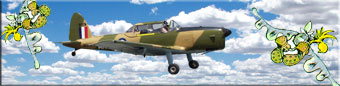
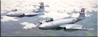
Painting Peter Connor, Aerial Photo Carl Perry Click on above pictures for more |
FLIGHT STABILITY ______________________________________ Training aeroplanes and general passenger carrying aeroplanes normally have a high degree of stability incorporated in their design, whilst the design characteristics of a military fighter aeroplane would favour a certain measure of responsiveness at the expense of stability. The recent availability of very sophisticated onboard computerised flight control systems, have allowed designers of military fighter aircraft, for the first time, to incorporate unstable flight characteristics in order to maximise responsiveness. Previously, it was not possible to consider such a configuration without the availability of computerised flight control systems. STABILITY IN THE ROLLING PLANE is achieved using; (i) Pendulum Effect, (ii) Dihedral Angle and (iii) Sweep-back (mainplane leading edge). These three design features are used in combination. Pendulum Effect consideration can be readily recognised in a high-wing aeroplane and the forces involved are obvious. Dihedral Angle refers to the angle measured between the two mainplane halves or tailplane halves (upswept wings configuration forming a shallow V is positive, down swept is negative). This text will refer only to the lateral stability achieved with 'positive' dihedral. When an aeroplane, in straight and level flight, is rolled by turbulence, (in the absence of a complimentary turning force) the aeroplane will slip towards the lower wing. As the aeroplane begins to slip, the relative airflow direction is changed - it is changed to the extent that the lower wing incurs a greater angle of attack than the higher wing, subsequently generating more lift (causing it to rise). Sweep-back refers to lateral sweep back of the mainplane leading edges. When an aeroplane in straight and level flight is caused to roll by turbulence (in the absence of a complimentary turning force) and then subsequently slips, the airflow across the lower wing becomes better aligned (the lower wing presents a broader span and the upper wing a narrower span) and generates more lift, causing it to rise. STABILITY IN THE YAWING PLANE is more simply achieved by the 'weathercock' effect of the rear fuselage and fin. STABILITY IN THE PITCHING PLANE is achieved with the use of an inbuilt relationship between the angle of incidence of the mainplane and the angle of incidence of the tailplane (Longitudinal Dihedral Angle). When an aeroplane, which is trimmed and established in straight and level flight is caused to 'pitch up' because of turbulence, there is, initially, due to inertia, an increase in the angle of attack on the mainplane and the tailplane. The tailplane incurs a greater proportionate increase in lift than does the mainplane because of the Longitudinal Dihedral Angle and subsequently, the tailplane rises. Typically, the mainplane would have a 4 degrees angle of incidence and the tailplane 1 degree. Example; (Assuming 4:1 relationship) If, in level flight, the mainplane had an angle of attack of 5degrees, then subsequently, the angle of attack on the tailplane would be 2 degrees (3 degrees difference in angles of incidence). If the aeroplane then experienced a pitch up of 2 degrees due to turbulence, the angle of attack on the mainplane would increase from 5 degrees to 7 degrees (40%) but the angle of attack on the tailplane, which would increase by the same amount, would increase from 2 degrees to 4 degrees (100%), causing the tailplane to rise. Similarly, with a pitch down, the relationship is in the same proportion and the stabilising force is effected in the correct sense. ______________________________________ MANOEUVRES ______________________________________ TURNS To create the necessary turning force, the aeroplane must be rolled around the longitudinal axis (banked) so that the perpendicular component of lift is 'tilted'. This creates a small vector at 90º to the perpendicular component of lift and it is this (horizontal) vector that provides the turning force. The rudder does not provide the main turning force, but rather provides a small supplementary force which is used to balance the aerodynamic forces involved whilst the aeroplane is banked and turning. When an aeroplane is banked in level flight, the perpendicular component of lift becomes tilted inwards and hence, the vertical component of lift is reduced (in level flight, lift = weight). When the rudder is used as a balancing force, the aeroplane responds by yawing around the vertical axis, (which is tilted inwards). This reduces the angle of attack which further reduces lift (the nose has lowered further below the horizontal due to the yaw whilst banked). Lift must be restored or the aeroplane will begin to lose height. This is normally accomplished by increasing the angle of attack, (elevator] however, as the angle of attack is increased, so also is drag increased. The increase in drag must now be offset by an increase in power, otherwise the aeroplane will lose speed (which would result in a further loss of lift). Once the desired bank angle has been reached using ailerons, it is necessary to 'hold off' the bank angle to prevent it increasing beyond the required amount. If this action is not taken, the bank angle will continue to increase because the outside wing moves faster through the air in the turn, thus incurring more lift (greater radius and distance to travel). A balanced level turn is a turn in which the rate of turn matches the angle of bank, the horizontal component of lift = centrifugal force and the vertical component of lift = weight. It can be noted that for a specific rate of turn at a specific airspeed, there is only one definitive angle of bank. Rudder and elevator alone will provide the necessary control forces to execute a turn, as is well known by model aeroplane pilots. However, the aerodynamic forces which act during a turn, would not be absolutely balanced in such a situation, with a noticeable imbalance occurring during entry and exit, where excessive yaw would be obvious In a 'rudder and elevator only' turn, the aeroplane initially responds to rudder deflection by yawing and commencing a flat, skidding turn. The secondary effect of the yaw causes the outside wing to rise. The outside wing rises because it generates more lift due to having a greater radius of turn and travelling faster. Thus, the aeroplane establishes a bank angle which in turn creates the primary turning force (the horizontal component of the tilted lift vector). SIDESLIP This manoeuvre is achieved by applying bank with ailerons and simultaneously applying opposite rudder to prevent turning. This procedure is commonly used on approach in aeroplane types not fitted with flaps (steeper approach angle without incurring an unwanted increase in airspeed.). ______________________________________ AEROBATICS ______________________________________ The realms of aerobatic flight are reached when the angle of bank exceeds 60 degrees [roll] or when the longitudinal axis exceeds 30 degrees [pitch] from the horizontal. Many aircraft [not models] have insufficient power to execute a loop without first diving to gain additional speed. This dive to gain additional speed, is also a common prerequisite for entry to other aerobatic manoeuvres. Many aircraft engines are fitted with float type carburettors and are subsequently unable to sustain power when subject to negative G loading. These restraints are virtually non existent for model aircraft pilots, who enjoy the advantages of continuous available power and of having a substantially greater power to weight relationship. Once the capability of basic aerobatic manoeuvres has been achieved by the [model aeroplane] pilot, an effort should be directed towards improving the coordination of control inputs, the precision of the manoeuvres and the pattern of the display. For the model aeroplane pilot, it is essential to strive for smooth, scale manoeuvres, because without this conscious effort, the results will be jerky and unrealistic. During aerobatic flight (in full size aeroplanes), high nose attitudes are frequently associated with high [full) power and low nose attitudes are frequently associated with reduced power - and it is to the advantage of the model aeroplane pilot, who is attempting to execute 'scale' manoeuvres, to recognise this situation even though its adoption may not be essential for the completion of the manoeuvre. The quality of an aerobatic manoeuvre can also be enhanced by recognising that the entry and exit form part of the manoeuvre. This section will deal with the following basic manoeuvres; Loop, Slow Roll, Barrel Roll, Snap Roll, Stall Turn, Spin. LOOP There are four basic variation of a loop; - inside round, inside square, outside round, outside square. The elevator is the primary flight control used, together with throttle. Positive G loading is maintained during an inside loop - whereas negative G loading is experienced during an outside loop. Aeroplanes fitted with float type carburettor engines are normally precluded from executing outside loops because of power loss during any negative G-load phase. The simplest aerobatic manoeuvre to execute is an inside round loop. However, it is necessary to appreciate a couple of basic points to achieve a precise manoeuvre. A poorly executed loop may have a flight path resembling a vertical oval, (or even a cigar) whereas appropriate throttle and elevator inputs, together with accurate speed and directional control will result in a precise manoeuvre. SLOW ROLL During a slow roll, the aeroplane revolves [slowly] around the longitudinal axis, maintaining an almost constant nose attitude, height and flight path. All three flight controls, together with throttle are used to coordinate the manoeuvre. Float type carburettor engines will not produce power during the phase where negative G loading is experienced, [inverted] and it is necessary to retard the throttle once inverted to protect the engine from a violent power surge on recovery of positive G. The basic task is to maintain the nose of the aeroplane on station throughout the 360 degree rotation. As the roll commences, it is necessary to progressively apply up elevator, simultaneously, with a progressive application of rudder against the direction of the roll (up elevator to prevent the nose from lowering and opposite rudder to prevent turning). As the aeroplane approaches 90 degrees of rotation, the up elevator is progressively eased back to neutral, and at the same time, the rudder deflection is progressively increased and offers a substitute for the tailplane (top rudder). As the roll proceeds past 90 degrees, and approaches the inverted position, top rudder is eased back to neutral whilst down elevator is progressively applied. (Substantial down elevator is required, to position the nose higher, ie., higher because the asymmetric aerofoil [mainplane] is now reversed, requiring a greater angle of attack to maintain the same value of lift - otherwise height will be lost.) The aeroplane is now inverted, and the rudder and elevator are used in a similar manner to maintain the nose on station throughout the completion of the second half of the roll. A variation of this manoeuvre entails momentary pauses during rotation. This variation is termed a 'hesitation roll' and may be a 'four point', 'eight point' or 'sixteen point'. The rolling movement is stopped and started, with precision, at the pre-determined points. Some aeroplane types have extremely responsive ailerons and are able to execute a fast, slow roll using ailerons alone - relying on inertia to maintain nose attitude and flight path - (aileron roll). However, the traditional 'slow roll' requires the skilled use and coordination of the three primary flight controls - and with float type carburettor engines, special considerations of throttle control. The slow roll is considered by many to be 'the classic aerobatic manoeuvre'. BARREL ROLL The flight path prescribed during this manoeuvre is akin to a corkscrew. The aeroplane does not simply revolve around its longitudinal axis, but in fact flies in coordinated flight, as though it was flying around the inside of a giant sized, horizontal cylinder, - maintaining positive G loading throughout the entire manoeuvre. The manoeuvre commences from straight and level flight on the centre alignment of the imaginary horizontal cylinder axis, and concludes with straight and level flight on the same axis. In this example, the aeroplane will execute a clockwise barrel roll. The entry is made from straight and level flight, commencing with a coordinated turn and dive to the left. The left turn and dive is progressively transformed into a climbing turn to the right, with increasing amounts of up elevator and throttle as the nose rises and airspeed diminishes. Up elevator is eased as the flight path goes over the top (inverted) to maintain a more symmetrical flight path (to prevent the nose dropping) - with throttle being reduced on descent, in some circumstances, to contain speed. The manoeuvre is concluded with the aeroplane climbing (right turn) towards the centre alignment of the imaginary horizontal cylinder axis, rolling out (left turn) and lowering the nose to resume straight and level flight along the original alignment. Positive G loading throughout this manoeuvre allows continuous application of power from float type carburettor engines. The alignment of the flight path is improved by attenuating complimentary rudder input - (creates a slight imbalance of turning forces but helps prevent the flight path straying off through the side of the imaginary cylinder). SNAP ROLL (Horizontal, vertical, inside, outside.) This manoeuvre invokes very high G loads and subsequently, many aeroplane types are precluded from attempting this manoeuvre because of structural limitations. The aim is to suddenly and decisively deprive one mainplane half of lift, so as to generate a strong rolling force. This effect is achieved with the following sequence on control inputs (inside manoeuvre). Sudden and course up elevator deflection is used to abruptly raise the nose which momentarily increases the angle of attack of the mainplane to the point of stall. Coordinated rudder (and opposite aileron) deflection provide the bias. With the correct mix and timing, a spectacular rolling effect is created. The 'snap roll' effect forms the basis for a variety of manoeuvres, with the horizontal, inside snap roll being the basic manoeuvre. The manoeuvre can be initiated with down elevator in which case the manoeuvre becomes an outside snap roll (eyeball popper). The manoeuvre can be entered from virtually any angle, right up through to the vertical, in which case it becomes a vertical snap roll (either inside or outside). Airspeed on entry, whilst not very high, can be considerably higher than normal stalling speed at 1G. STALL TURN This manoeuvre is most graceful to observe and is quite simple to execute. The manoeuvre is usually entered from a dive, pulling up smoothly into a vertical climb while progressively increasing the throttle to full power. The aeroplane is held in a vertical climb as the airspeed decays - and when the airspeed has reduced to a little above normal stall speed, full rudder deflection is applied in the intended direction. The aeroplane will turn (yaw) in response to the slipstream (from full throttle) acting on full rudder deflection - and with the mainplane remaining in the vertical plane, the nose will gracefully fall through 180º to vertically downwards. As the nose passes through the horizon, the throttle is closed, (to contain speed) and the rudder deflection is progressively returned to neutral. The aeroplane will continue to yaw through the remaining 90º to assume a vertical nose down attitude, from where a recovery is made. SPIN This manoeuvre is one of the most spectacular. A normal spin is entered from a nose high attitude at the point of stall with the throttle closed. As the aeroplane is about to stall, full rudder deflection is applied in the intended direction of spin so as to create a decisive yaw. At this point, the elevator should be at maximum up deflection. In some aeroplane types, a more decisive wing drop and entry can be achieved by applying full opposite aileron simultaneously with rudder application so as to further increase the angle of attack on the inside wing (down aileron increases angle of attack) promoting a more decisive stall and loss of lift on the inside wing. (The controls are maintained in these positions throughout the duration of the spin.) As the aeroplane yaws at the point of entry, the outside wing generates slightly more lift and rises. As the inside wing drops, its angle of attack is increased even more, becoming further stalled (by comparison with the outside wing) - and as a consequence of the increased angle of attack, incurs an increase in drag, which contributes to the yaw. Thus, auto rotation is established. This condition is maintained during the spin, with the airspeed static at a very low value (about normal stalling speed). During the spin, the aeroplane will have a steep nose down attitude, the flight controls will be ineffective and the aeroplane will vibrate and shake due to the turbulent airflow - (if it is his or her first spin, the pilot may also shake and vibrate). Recovery technique is quite specific in respect of the control inputs and sequence; (i) full opposite rudder (and maintain until rotation ceases), (ii) neutralise the ailerons (and maintain until rotation ceases), (iii) progressively apply down elevator through to full deflection (and maintain until rotations ceases). Some aeroplane types respond slowly to the recovery procedure and may continue in the spin for a further revolution or two after the recovery inputs have been made. When rotation ceases, the three primary flight controls are moved to neutral positions and the mainplane rapidly becomes unstalled. A recovery from the ensuing dive is then effected. Spins are forbidden in some aeroplane types due to structural limitations - and in some cases are forbidden because recovery may be difficult, or even impossible. To use the WW2 Hawker Tempest as an example again - the instruction to the pilot was that if he found himself in a spin, he was to bail out and not attempt a recovery. Some aeroplane types are capable of an inverted spin - with the pilot getting a pretty wild ride, incurring negative G on the outside/underside. ______________________________________ DISPELLING SOME MISCONCEPTIONS ______________________________________ An aeroplane flies in a three dimensional environment - within a body of air. When the body of air is moving (horizontally) it is manifest as wind (relative to a fixed observation on the ground). When wind conditions exist, the flight path of the aeroplane, relative to the earth, is effected, but the aerodynamic considerations of airspeed, climb rate and rate of turn etc. are not effected. Much confusion surrounds this particular aspect and this section aims at resolving some of the misconceptions. CLIMB/DESCENT For a given rate of climb, (eg. 500 fpm) the angle of climb will be greater with a head wind component and less with a tail wind component. When observing an aeroplane (from the ground) that is established in a climb, a misconception can occur when the aeroplane turns from downwind to up wind (common event with model aeroplanes). As the aeroplane turns from downwind to upwind, the angle of climb increases (reduced ground speed) and the misconception is that the rate of climb has increased. For a given rate of descent, the angle of descent will be greater with a head wind component and less with a tail wind component. The misconception is founded on the same considerations (differing ground speed) as referred to above. HEADING, DRIFT, TMG The Proposition If a motor car was to drive along a straight stretch of road in a northerly direction, say during a trip from Adelaide to Darwin, whilst there was a 40 knot westerly wind blowing, the motor car would experience more wind blowing on its left side than its right side. True! If an aeroplane was to fly immediately above the motor car, and to maintain the same track across the ground, it would not experience more wind blowing on the left side than on the right side even though the same wind velocity prevailed. True! The explanation The body of air is moving in relation to the ground, not in relation to the aeroplane. The aeroplane flies within this body of air, complying with the same laws of aerodynamics whether or not the body of air is moving in relation to the ground. The airflow passing down each side of the fuselage is aligned with the longitudinal axis of the aeroplane. In this example, the body of air is moving to the right (east) at 40 knots and if no adjustment is made to the northerly heading, the aeroplane will be 40 miles to the right (east) of the track after a period of one hour. (The necessary adjustment would approximate the drift angle). If such an adjustment were to be made, then the aeroplane will appear (to an observer beneath, in the car) to crab along the track, with its nose to the left of the track as it maintains the same track as the car. However, the relative airflow will be aligned with the longitudinal axis of the aeroplane. TURNS AT LOW LEVEL (IN WIND CONDITIONS) ______________________________________ When an aeroplane executes a turn from downwind to upwind, the radius of the turn in relation to the ground, will be much greater than when executing a turn from upwind to downwind (same rate of turn). The misconception here is that the aerodynamic forces (in the turns) are different - when in fact they are not. The misconception is only manifest at low altitude - and of course for model aeroplane pilots, exists virtually all of the time. The danger that stems from this misconception (real aeroplanes) becomes a reality during a low altitude turn from downwind to upwind. This scenario has been responsible for many aeroplane accidents. When the aeroplane enters a turn from downwind, at low level, the observation by the pilot is that the aeroplane is skidding out. The natural response to this observation is to increase the angle of bank to redeem the increasing radius of the turn. It can be assumed that the turn would normally be initiated with balanced forces, so this being the case, the stage is set to 'over bank'. If the angle of bank was simply increased in this situation, the vertical component of lift would be decreased, and the aeroplane would slip (towards the lower wing). The loss in altitude would not be expected and if the aeroplane was at a very low altitude, the slip may not be detected in sufficient time to prevent contact with the ground. Bruce Wall copyright 1982 |